| |
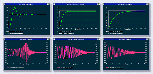
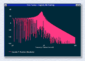
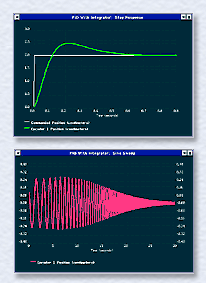
Students design and implement under-, critical-, and overdamped systems using equations provided in the manual. The step responses are measured and the effect of damping ratio on rise time and overshoot is observed. ECP's sine sweep function is used to obtain an experimental frequency response (lower row of Figure 1). The students examine the two data sets and correlate the time and frequency response behaviors. The underdamped resonance corresponds to the step oscillation. Reduced bandwidth with increased damping correlates to the slower step rise time. The sine sweep data plotted in Figure 1 uses linear time and amplitude scaling. This best reflects the motion actually seen. Using ECP's unique Db amplitude and log-frequency plotting options, the same data (see Figure 2, underdamped case) displays the classical Bode magnitude characteristics: unity DC gain, resonance near the natural frequency, and -40 Db per decade high frequency attenuation. By witnessing the actual system motion, and using a variety of data scaling options, students are given a clear physical interpretation of fundamental phase and gain characteristics. Figure 3 gives the results where integral action is added to the critically damped system. As can be seen, the step response exhibits the classical overshoot and zero steady state error. The frequency response shows a slight resonance and relatively high bandwidth corresponding to the step overshoot and more rapid rise time. These exercises introduce the student to several important concepts: the distinct P, I, and D control actions, the effect of the corresponding gains on the closed loop poles, and fundamental properties of transient and frequency responses. (Don't you wish these learning tools were available when you were an undergrad? We at ECP sure do!) |