This experiment vividly demonstrates key properties of multi-DOF systems and the ability of closed loop control to compensate for adverse plant dynamics. LQR synthesis is employed to produce control designs for a SIMO flexible plant. A family of controllers is generated and tested. The root-locus as the LQR error weighting is varied is studied and the resulting step and frequency responses are witnessed on the system.
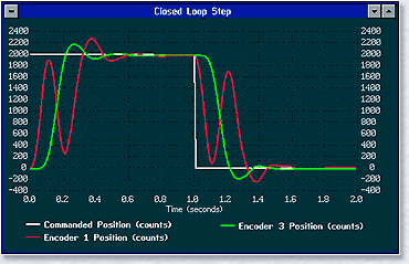
The LQR error weighting is solely on the state of position of the most distant non-collocated inertia (e.g. the third inertia from the actuator for 3 DOF plants) and hence its motion is minimized in the synthesis. As seen in the upper plot, the resulting step response shows the collocated inertia (encoder #1) moving wildly in order to minimize the error at the noncollocated inertia (encoder #3).
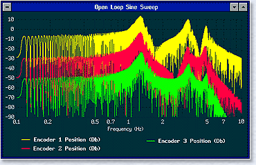
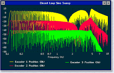
The second and third plots give the experimental Bode magnitude responses of the open and closed loop systems using ECP's unique sine sweep and Db measurement functions (individual curves displaced 20 Db for clarity).
Several important properties of flexible plants are clearly seen in the second plot . . .
- The plant has as many resonant natural frequencies as its DOF (common to all output locations).
- The first inertia has 2 lightly damped zero pairs interspersed between the poles and has -40
Db/dec. high frequency roll-off
- The second inertia has a single zero pair and -80 Db/dec. roll-off
- The third inertia has no zeros and -120 Db/dec. roll-off
The third plot shows the frequency response under closed loop LQR control. As can be seen from the plot . . .
- The plant zeros are invariant under closed loop control
- The noncollocated (encoder #3) response is well flattened by the control but has relatively low frequency roll-off. This corresponds to the well-behaved step response with slow rise time in the upper plot.
- The collocated response (encoder #1) shows resonant poles and anti-resonant zeros with higher bandwidth and correlates with the irregular step response with rapid rise time.
In addition to the important principles demonstrated by examination of the acquired data, students are afforded a unique physical insight by witnessing the corresponding system motion during the acutal maneuvers.


